Weiss
Engineering
SPEARHEADING DIGITAL AUDIO
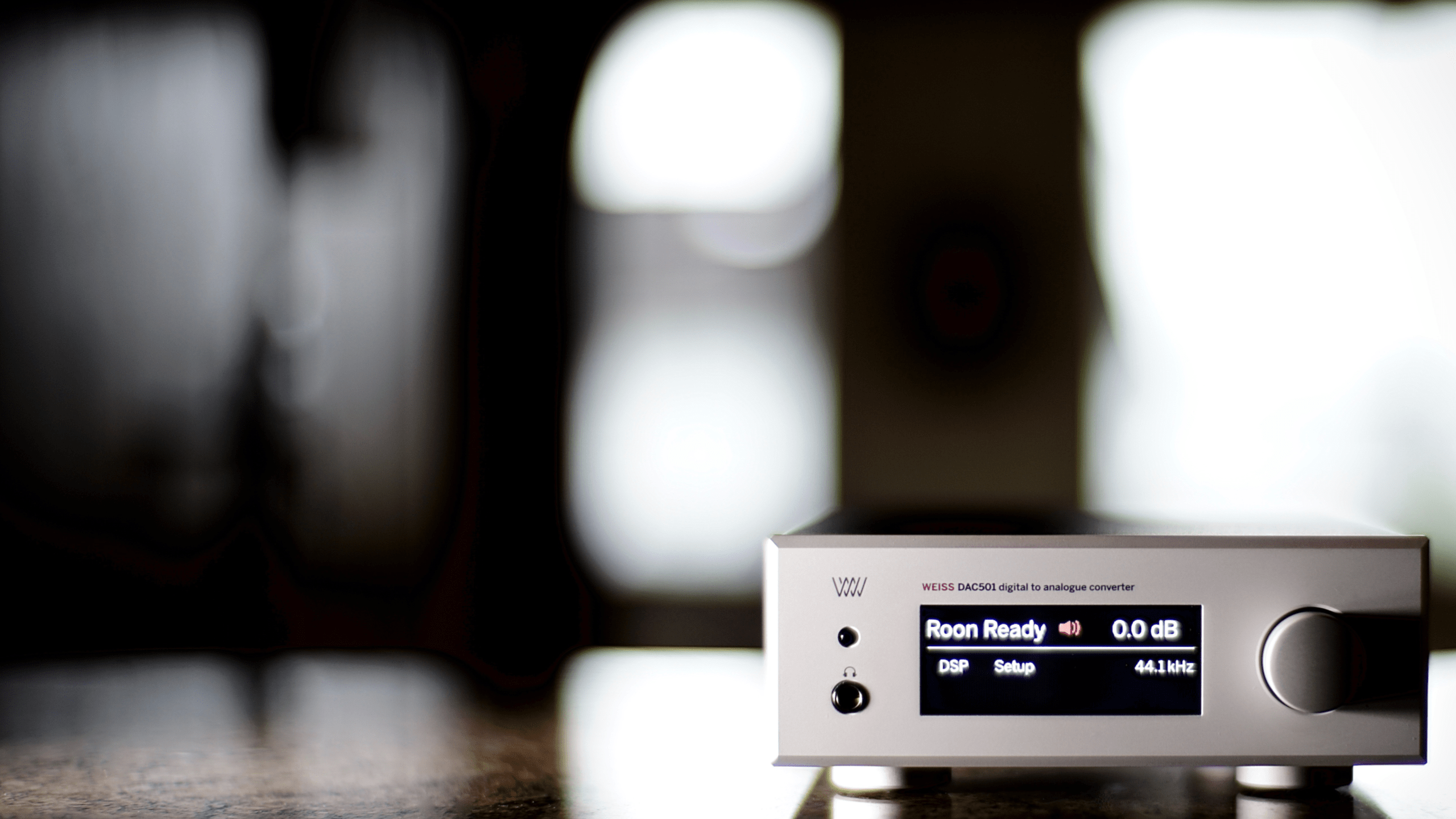
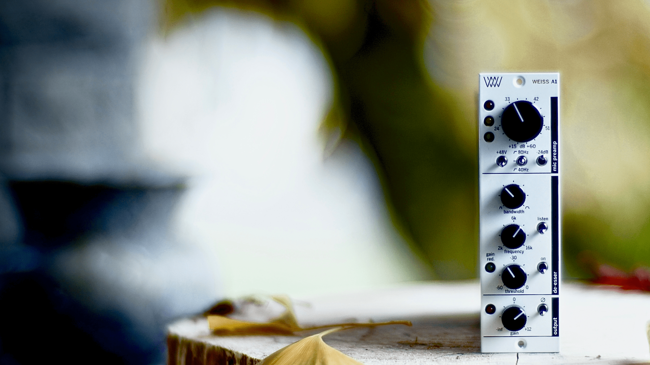
Led by Grammy award-winning audio pioneer Daniel Weiss, Weiss Engineering has spent decades developing cutting-edge digital audio equipment for professional audio engineering and high-end home systems. All products are manufactured in Switzerland.
Weiss Dealer
Locate Your
Nearest Weiss Reseller
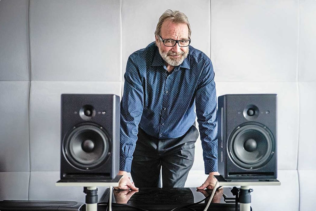
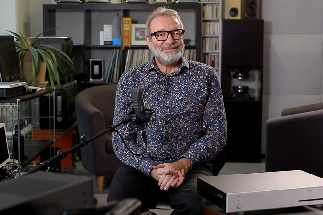
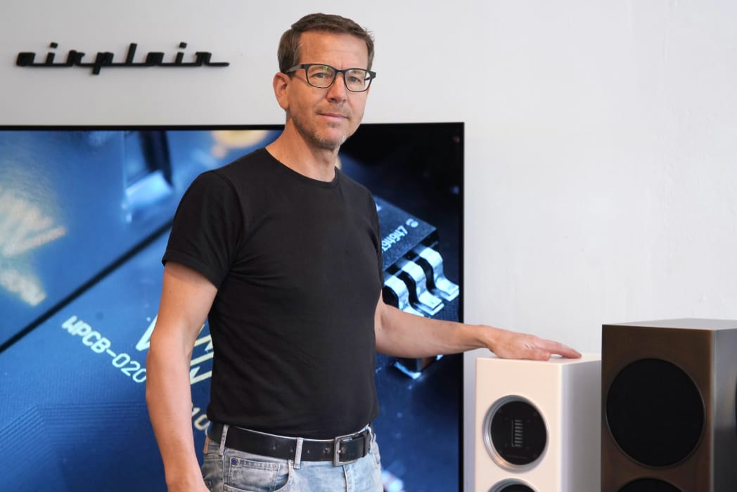
MEET DANIEL WEISS
Read the interview with Daniel Weiss – the man behind Weiss Engineering and widely regarded as one of the pioneers of audio technology.